Four-Wheel Counterbalance Electric Forklift: What Overload Protection Settings Reveal About Hydraulic System Configuration
News 07/11/2026
Overload protection is often treated as a safety checkbox, but its settings expose how the hydraulic system of a four-wheel counterbalance electric forklift is configured, tuned, and limited. The protection threshold, the sensing method, and the response behavior all depend on hydraulic pressure limits, valve design, mast and carriage geometry, and the load-sensing logic built into the machine. Reading those settings the right way helps buyers ask better questions, compare configurations honestly, and avoid mistaking a conservative setting for a stronger machine. This article explains what the settings reveal, how to interpret them during selection, and which data you still need from the manufacturer before deciding.
What Overload Protection Settings Actually Control on a Counterbalance Truck
On a four-wheel counterbalance electric forklift, rated capacity is defined at a specific load center and lift height. Overload protection is the system that detects when the actual load or the resulting hydraulic pressure exceeds what the configuration allows, and then limits or blocks the hazardous movement. The settings behind that behavior are not a single number. They usually combine a pressure threshold in the hydraulic circuit, a load-sensing arrangement, and a control response such as restricting lift or blocking travel.
What the settings reveal is the design envelope the manufacturer chose. A pressure limit reflects the hydraulic system’s working pressure, the relief valve setting, and the structural assumptions behind the mast, carriage, and cylinders. The response behavior reflects how the control system prioritizes stability over productivity. When a supplier can explain these settings clearly, it usually means the hydraulic configuration has been engineered as a system rather than assembled from generic parts.
Three practical points follow. First, overload protection is tied to load center and lift height, not to a bare weight figure. Second, the setting is a limit, not a performance claim. Third, the same nominal capacity can be protected differently across configurations, so the settings must be read together with the mast, attachment, and hydraulic layout.
How Hydraulic Configuration Shapes the Protection Threshold
The protection threshold is the visible output of several hydraulic decisions. The table below summarizes the main relationships, the risks each one addresses, and the documentation a buyer should request.
| Configuration element | What it reveals about the hydraulic system | Risk addressed | Documentation to request |
|---|---|---|---|
| Relief valve setting | Working pressure ceiling and the margin between normal operation and protection | Pressure spikes, cylinder and hose stress | Hydraulic schematic and relief valve specification |
| Load-sensing or pressure-sensing method | Whether protection responds to actual load or to circuit pressure alone | False trips, undetected overload at long load centers | Description of the sensing principle and its calibration |
| Control response (lift limit, travel inhibit, alarm) | How the control system prioritizes stability and how operators experience the limit | Tip-over, mast overload, unsafe travel with raised load | Behavior description and operator warning sequence |
| Mast and carriage geometry | The load center and lift height assumptions built into the threshold | Reduced remaining capacity with height or attachments | Capacity chart by load center and lift height |
| Attachment provisions | Whether the hydraulic circuit and protection are configured to match added functions | Overload from attachment weight and shifted load center | Derating data and attachment compatibility statement |
Two conclusions are safe to draw from this table. A pressure-based threshold alone does not automatically account for a long load center, so the capacity chart matters as much as the setting. And an attachment changes both the load and the geometry, so the protection configuration must be reviewed whenever an attachment is added.
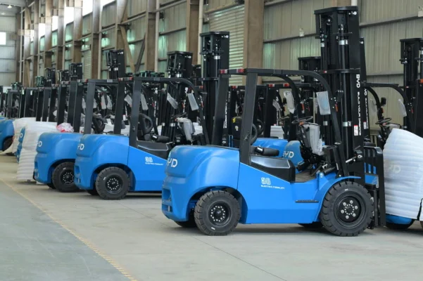
What the settings do not reveal is real structural margin. A higher threshold does not mean a stronger mast, and a lower threshold does not mean a weaker truck. The setting is one part of a coordinated design, and it should be read alongside the capacity chart and the manufacturer’s hydraulic documentation.
Reading Settings During Selection: A Practical Checklist
Selection conversations become more useful when overload protection is treated as a configuration question rather than a specification line. The following sequence works well when evaluating a four-wheel counterbalance electric forklift.
1. Start from the real load, not the rated capacity
Record the heaviest load, the load center of the actual pallet or attachment, and the lift height at which the load must be handled. Rated capacity at a short load center does not transfer automatically to a long load or a high lift. Ask how the protection threshold is adjusted when the load center and lift height change.
2. Confirm the sensing method and its limits
Ask whether protection responds to hydraulic pressure, to a load-sensing arrangement, or to a combination. Then ask what conditions can produce a false indication, such as cold hydraulic oil, a partially extended cylinder, or an attachment that shifts the load. The answer shows how well the configuration has been matched to real operations.
3. Verify the response behavior
Clarify what happens when the threshold is reached: lift restriction, travel inhibition, an audible or visual warning, or a combination. Confirm the sequence and whether the operator can safely lower and reposition the load. A protection system that leaves the operator without a safe recovery path creates its own risk.
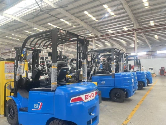
4. Review the hydraulic layout as a whole
Request the hydraulic schematic, the relief valve specification, and the maintenance points that affect protection, such as filter intervals and oil condition checks. Protection settings depend on the circuit behaving as designed, so maintenance requirements belong in the selection discussion.
5. Check the boundary conditions
Ask about ambient temperature range, duty cycle, floor conditions, and ramp use. Cold oil and sustained heavy duty can change how the hydraulic system behaves, and the manufacturer should state the operating conditions under which the protection settings remain valid. If those conditions are not documented, treat them as open items rather than assumptions.
A hypothetical application shows why this matters. Imagine a warehouse that handles pallets of variable weight and occasionally uses an attachment. If the truck is specified only by rated capacity, the protection threshold may be tuned to a load center that no longer matches the attachment. Reviewing the settings, the capacity chart, and the derating data together would reveal that mismatch before delivery rather than after an incident.
Frequently Asked Questions
Does a higher overload protection threshold mean the forklift can handle more weight?
No. The threshold is a limit within a coordinated hydraulic and structural design, not a capacity rating. Actual capacity depends on load center, lift height, attachment, and the manufacturer’s capacity chart. A higher setting without a matching chart and structure would not increase safe handling capability.
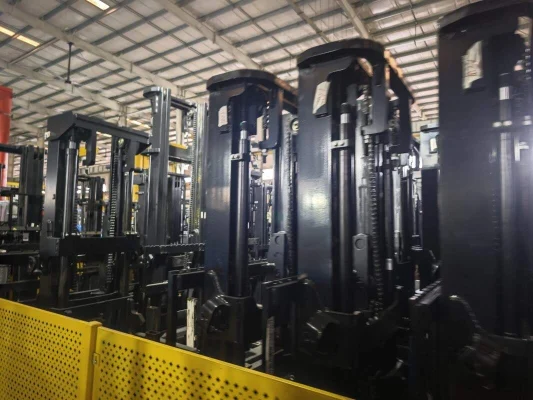
Why does the same nominal capacity truck behave differently when overloaded?
Because protection settings, sensing methods, and control responses vary with hydraulic configuration and mast geometry. Two trucks with the same nominal capacity can have different thresholds and different responses. Compare the capacity charts and the hydraulic documentation, not just the capacity label.
Can overload protection settings be changed after delivery?
Any change should come from the manufacturer or an authorized service provider with the correct documentation. Settings are tied to the hydraulic circuit and structural assumptions, so unauthorized adjustment can defeat the protection or create unsafe behavior. Ask the supplier what is adjustable and under what conditions.
What should I ask a supplier before choosing a configuration?
Ask how the threshold is determined, which sensing method is used, what the response sequence is, how attachments affect derating, and which operating conditions the settings assume. Also request the capacity chart, hydraulic schematic, and maintenance requirements. If the supplier cannot explain these points, the configuration is not fully documented.
Before purchase, complete your own data list: heaviest load, load center, lift height, attachment use, aisle and floor conditions, ramp use, ambient temperature range, duty cycle, and charging arrangements. Then ask the supplier to confirm the protection configuration against those conditions and to state any limits in writing. That conversation is the most reliable way to judge whether the hydraulic system and its overload protection are genuinely matched to your operation.